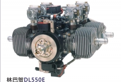
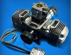
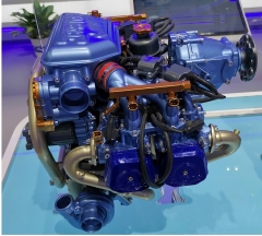
Limbach L550E is a four-cylinder, two-stroke, horizontally opposed engine, with excellent performance, outstanding reliability and excellent power-to-weight ratio, which has been used in many fixed-wing unmanned stages in France, South Africa, Thailand, Singapore and domestic Chinese Academy of Sciences and aerospace systems. In order to meet the demand for long endurance and high altitude, Limbach has launched the L550EF EFI engine, which has already been applied in many plateau-type unmanned aerial vehicles, and the L550E engine can be used in 200-450kg take-off weight taxiing, vertical take-off and landing fixed-wing unmanned aerial vehicles, as well as 100-160kg rotorcraft and helicopters.
Limbach L550E is an air-cooled horizontally-opposed four-cylinder two-stroke petrol engine developing 37 kW (50 hp) at 7500 rpm which can drive a propeller either directly or geared. It employs a single magneto ignition, four carburettors, and is lubricated by oil mixture lubrication with a fuel to oil ratio of 25:1 for mineral oil or 50:1 for synthetic oil.
Limbach L550E Specifications
Type: Four cylinder, two stroke aircraft engine
Bore: 66 mm (2.60 in)
Stroke: 40 mm (1.57 in)
Displacement: 548 cc (33.4 cu in)
Length: 300 mm (11.8 in)
Width: 410 mm (16.1 in)
Height: 301 mm (11.9 in)
Dry weight: 16 kg (35 lb)
Components
Fuel type: 90 RON octane unleaded petrol or 100 LL Avgas
Oil system: oil mixture lubrication, 25:1 fuel to oil ratio for mineral oil, 50:1 for synthetic oil
Cooling system: air
Performance
Power output: 37 kW (50 hp)
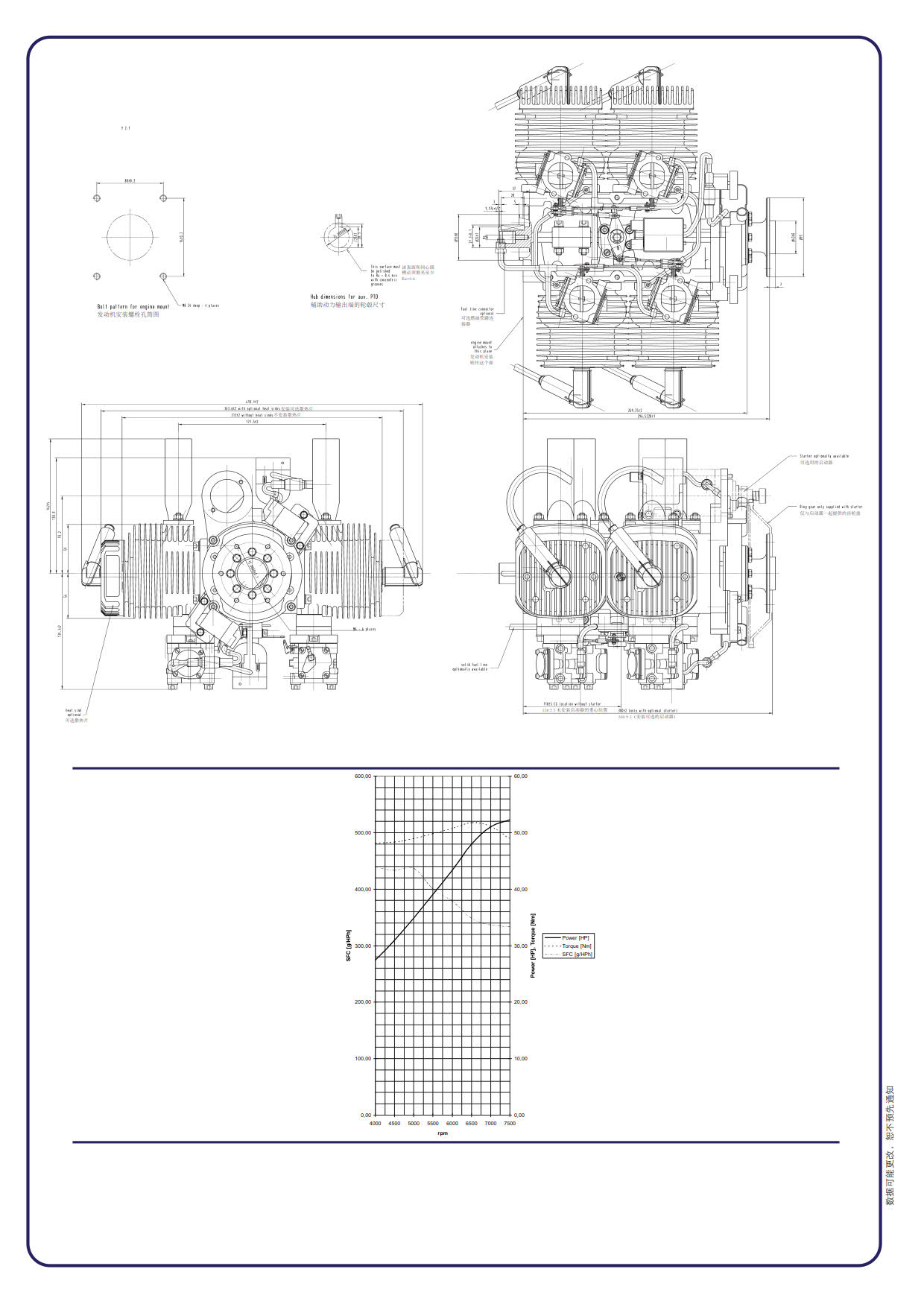
Limbach L550E Mechanical Dimensions and Altitude and Power Figures
Limbach l550E Engine Test Bench Test Instruction - Pre-Engine Test Installation
1、Preparation before engine installation
First, place the Limbach L550E engine on a flat table and prepare the necessary accessories and tools for installation.
2、Engine installation on the test bench
2.1. Assemble 4 buffer spacers to the buffer pad mounting on the engine base respectively; install the engine mounting seat so that the rudder pull rod can pass through the mounting seat holes; tighten and connect the engine mounting seat with the buffer pad through the supporting bolts.
2.2. Install the 4 mounting studs on the mounting end plates at the front of the test stand, and use the supporting bolts for fastening connection.
2.3. Use special lifting tools to lift the engine; adjust the lifting height of the engine to keep the engine and the mounting surface of the test bench at the same height as far as possible; adjust the position of the engine so that the holes of the engine mounting seat and the holes of the mounting studs of the test bench are aligned; and use matching bolts to fasten the connection.
2.4. The propeller should be installed in such a way that the heading on the propeller is the same as that of the airplane; use the matching mounting bolts and propeller pads for assembly; tighten the bolts in turn.
3、Engine electric vapor control assembly and connection
3.1. Engine throttle servo drive (rudder) installation
The servo mount is installed on the test bench head end plate; the servo is installed and fixed on the servo mount; the servo rocker arm is connected to the servo lever; the servo signal line is connected to the throttle control signal interface of the test bench through the extension cable.
3.2 Magneto ignition system assembly
There are two sets of magneto ignition system, one set of magneto ignition system of the two spark plug cap into the engine front end of the left and right side of the cylinder on the spark plugs, press in place; another set of magneto ignition system of the two spark plug cap into the engine back end of the left and right side of the cylinder on the spark plugs, press in place.
Use tie wraps to secure the two magneto ignition systems, to the engine mounts;
Connect the 2-way magneto ignition system hitch wires in parallel with the wire extensions and use insulating tape for adhesive sealing;
The other end of the wire extension line is connected to the ignition switch, the red ignition switch is an emergency switch; the ignition switch wire and the engine shell through the bolt fastening connection together; the ignition switch line connection to meet the press circuit for the on state, pop up for the off state; the ignition connector on the engine were connected to the two sets of magneto ignition system ignition connector;
3.3 Installation of starter motor circuit
Connect the positive terminal of the power cord to the positive terminal of the starter motor; connect the negative terminal of the power cord to the casing of the starter motor.
The starter motor through the relay control circuit access and disconnection, the relay signal control line into the electric starter switch, the green button for the electric starter switch button, the line connection to meet the press for the access state, pop up for the disconnection state
3.4 Exhaust pipe installation
Install the special gasket for the exhaust pipe at the engine exhaust port, and then assemble the exhaust pipe to the engine exhaust port.
Use nuts to fasten the exhaust pipe.
3.5. Engine Oil Connections
Install 4-channel oil inlet pipe on the engine; and merge the 4-channel oil inlet pipe into 1-channel and connect it with the oil filter at the outlet end of the oil quantity sensor.
Limbach L550E engine installation as well as electrical and oil line connections are complete, thank you for watching this engine test installation!